Honda Civic manuals

Honda Civic Service Manual: Engine Oil Pan Removal and Installation (K24Z7)

Honda Civic Service Manual / Powertrain / Engine / Engine Lubrication / Engine Oil Pan Removal and Installation (K24Z7)

1111Q1

1. Warm Up The Engine

1.

Warm up the engine.


2. Upper Torque Rod Mounting Bolt - Loosen

1.

Loosen the upper torque rod mounting bolt (A).


3. Vehicle Lift

1.

Raise the vehicle on a lift, and make sure it is securely supported.


4. Engine Oil - Replacement


1.

Remove the drain bolt (A), and drain the engine oil.


2.

Reinstall the drain bolt with a new washer (B) and torque to specification.


5. Front Wheel

1.

Remove both front wheels.


6. Steering Joint Cover

1.

Remove the steering joint cover (A).


7. Steering Column Lower Slide Shaft - Hold


1.

Set the steering column to the center tilt position, and to the center telescopic position.


2.

Hold the lower slide shaft (A) on the column with a piece of wire (B) between the joint yoke (C) of the lower slide shaft and the joint yoke (D) of the upper shaft to prevent the lower slider shaft from pulling out.


8. Steering Joint Bolt - Loosen

1.

Loosen the steering joint bolt (A).


9. Steering Wheel Hold


1.

Center the steering wheel spoke angle.


2.

Install a commercially available steering wheel holder tool (A).


10. Steering Joint - Disconnection


1.

Remove the steering joint bolt (A).


2.

Disconnect the steering joint (B) from the pinion shaft.


NOTE:

If the center guide (C) is in place and has not moved, leave it in place.

If the center guide has come off, discard it.


11. Splash Shield

1.

Remove the splash shield (A).


12. Front Stabilizer Ball Joint - Disconnection, Both Lower Arm Side


1.

Remove the flange nut (A) while holding the respective joint pin (B) with a hex wrench (C).


2.

Remove the stabilizer link (D).


13. Lower Arm Joint - Disconnection, Both Knuckle Side


1.

Remove the flange bolt and the self-locking nuts on both sides.


2.

Separate the lower arm using a pry bar on both sides.


14. Engine Support Hanger

o7aaksnaai2o

1.

Attach the universal lifting eyelet to the cylinder head.


2.

Install the engine support hanger as shown.


3.

Attach the hook to the slotted hole in the universal lifting eyelet.


4.

Tighten the wing nut (A) by hand, and lift and support the engine/transmission.


NOTE: Be careful when working around the windshield.


15. Lower Torque Rod - Disconnection

1.

Remove the lower torque rod mounting bolts.


16. Front Sub Frame - Move

1.

Loosen the mid stiffener mounting bolt (A) on both sides.


FRONT


REAR

2.

Loosen the front subframe mounting bolts (A) on both sides.


17. Lower Torque Rod Bracket

1.

Remove the lower torque rod bracket.


18. Clutch Cover

1.

Remove the clutch case cover and the transmission mounting bolts.


19. Oil Pan Assembly


1.

Remove the bolts securing the oil pan.


2.

Using a flat blade screwdriver, separate the oil pan from the engine block in the places shown.


3.

Remove the oil pan.


1. Oil Pan Assembly


1.

Remove all of the old liquid gasket from the oil pan mating surfaces, the bolts, and the bolt holes.


2.

Clean and dry the oil pan mating surfaces.


3.

Apply liquid gasket (P/N 08718-0004 or 08718-0009) to the engine block mating surface of the oil pan and to the inner threads of the bolt holes. Install the component within 5 minutes of applying the liquid gasket.


NOTE:

Apply liquid gasket about 2.5 mm (0.098 in) diameter bead along the broken line (A).

If too much time has passed after applying the liquid gasket, remove the old liquid gasket and residue, then reapply new liquid gasket.


4.

Install the oil pan on the engine block.


5.

Tighten the bolts in three steps. In the final step, torque all bolts, in sequence, to 12 N·m (1.2 kgf·m, 9 lbf·ft). Wipe off the excess liquid gasket on the each side of crankshaft pulley and the flywheel/drive plate.


NOTE:

Wait at least 30 minutes before filling the engine with oil.

Do not run the engine for at least 3 hours after installing the oil pan.


2. Clutch Cover

1.

Install the clutch case cover and the transmission mounting bolts.


3. Lower Torque Rod Bracket

1.

Install the lower torque rod bracket using new bolts.


4. Front Sub Frame - Move

REAR


FRONT

1.

Loosely install the new front subframe mounting bolts (A) on both sides.


5. Front Subframe Assembly

1.

Loosely install the new front subframe mounting bolts (A).


n-m77lm41!


2.

Insert the subframe alignment pin (B) through the positioning hole (C) on the right front subframe, and into the positioning hole (D) on the body, then loosely tighten the subframe right front mounting bolt.


3.

Insert the subframe alignment pin through the positioning slot on the left front subframe, and into the positioning hole on the body, then loosely tighten the subframe left front mounting bolt.


4.

Tighten the subframe mounting bolts to the specified torque values starting with the right front subframe mounting bolt. Use the subframe alignment pin when tightening the front side subframe mounting bolts.


5.

Check all of the subframe mounting bolts, and retighten if necessary.


NOTE: Tighten the bolts in the sequence shown.


6. Lower Torque Rod - Reconnection

1.

Loosely install the new lower torque rod mounting bolts.


7. Engine Support Hanger

o7aaksnaai2o


1.

Remove the engine support hanger.


2.

Remove the universal lifting eyelet.


8. Lower Torque Rod Mounting Bolt - Tighten


1.

Loosen the lower torque mount mounting bolt.


2.

Tighten the lower torque rod mount mounting bolts in the numbered sequence shown.


9. Lower Arm Joint - Reconnection, Both Knuckle Side

mm


1.

Connect the lower arm (A) to the knuckle on both sides using new flange bolt and new self-locking nuts.


2.

After lightly tightening all three fasteners, tighten them to the specified torque in the following order; the nut on the front (B), the nut on the rear (C), then the bolt (D).


10. Front Stabilizer Ball Joint - Reconnection, Both Lower Arm Side

27m.27


1.

Install the stabilizer link (A) on the stabilizer bar (B) with the joint pins set at the center of their range of movement on both sides.


2.

Install the new self-locking nut (C) on both sides.


3.

Tighten it to the specified torque while holding the respective joint pin (D) with a hex wrench (E) on both sides.


11. Upper Torque Rod - Tighten

i2mm

1.

Tighten the upper torque rod mounting bolt.


12. Steering Column Lower Slide Shaft - Release

1.

Cut the wire (A).


13. Steering Wheel Release

1.

Remove the steering wheel holder tool (A).


14. Steering Joint - Reconnection


1.

Set the rack in the straight ahead driving position.


2.

Slip the lower end of the steering joint (A) onto the pinion shaft (B).


NOTE:

Pinion shaft with center guide: Install the steering joint by aligning the center guide (C).

Pinion shaft without center guide: Position the steering column by aligning the gap (D) within the angle.


3.

Align the bolt hole (A) on the steering joint with the groove (B) around the pinion shaft.


4.

Loosely install the steering joint bolt (C).


5.

Be sure that the joint bolt is securely in the groove in the pinion shaft.


6.

Pull on the steering joint to make sure that the steering joint is fully seated.


15. Steering Joint Bolt - Tighten

mm:.o21

1.

Tighten the steering joint bolt (A) to the specified torque.


16. Steering Joint Cover

1.

Install the steering joint cover (A) in the sequence shown.


17. Front Wheel

mmmln-mnomm

1.

Install both front wheels.


NOTE: Before installing the wheel, clean the mating surfaces between the brake disc and the inside of the wheel.


18. Engine Oil - Replacement

1.

Refill the engine with the recommended engine oil.


Except K24Z7 engine

Capacity

At Oil Change:

3.5 L (3.7 US qt)

At Oil Change including Filter:

3.7 L (3.9 US qt)

After Engine Overhaul:

4.5 L (4.8 US qt)


K24Z7 engine

Capacity

At Oil Change:

4.0 L (4.2 US qt)

At Oil Change including Filter:

4.2 L (4.4 US qt)

After Engine Overhaul:

5.3 L (5.6 US qt)


19. Splash Shield

1.

Install the splash shield (A).


20. Pre-Alignment Checks

For proper inspection and adjustment of the wheel alignment, do these checks:


1.

Release the parking brake to avoid an incorrect measurement.


2.

Make sure the suspension is not modified.


3.

Make sure the fuel tank is full, and that the tire repair kit, the spare tire, the jack, and the tools are in place on the vehicle.


4.

Check the tire size and tire pressure according to tire information.


21. Caster - Inspection

Use commercially available computerized four wheel alignment equipment to measure wheel alignment (caster, camber, toe, and turning angle). Follow the equipment manufacturer's instructions.


1.

Check the caster angle.


USA and Canada models

Caster angle:


Except Si:

5 ° 19 ’±30 ’


Si (Without 18 inch wheel):

5 ° 22 ’±30 ’


Si (With 18 inch wheel):

5 ° 15 ’±30 ’


Mexico models

Caster angle:


Without 18 inch wheel:

5 ° 10 ’±30 ’


With 18 inch wheel:

5 ° 6 ’±30 ’


If the measurement is within specifications, measure the front camber angle.

If the measurement is not within specifications, check for bent or damaged suspension components.


22. Camber - Inspection

Use commercially available computerized four wheel alignment equipment to measure wheel alignment (caster, camber, toe, and turning angle). Follow the equipment manufacturer's instructions.


1.

Check the camber angle.


USA and Canada models

Camber angle:


Except Si:


Front:

0 ° 00 ’±30 ’


Rear:

-0 ° 45 ’±45 ’


Si (Without 18 inch wheel):


Front:

-0 ° 04 ’±30 ’


Rear:

-0 ° 52 ’±45 ’


Si (With 18 inch wheel):


Front:

-0 ° 18 ’±30 ’


Rear:

-0 ° 45 ’±45 ’

(Maximum difference between the front right and left side: 0 ° 45 ’)


Mexico models

Camber angle:


Front:

0 ° 20 ’±30 ’


Rear:

-0 ° 22 ’±45 ’

(Maximum difference between the front right and left side: 0 ° 45 ’)


If the measurement is within specification, measure the toe-in.

If the measurement for the front camber is not within the specification, go to front camber adjustment.

If the measurement for the rear camber is not within the specification, check for bent or damaged suspension components.


23. Front Toe - Inspection

Use commercially available computerized four wheel alignment equipment to measure wheel alignment (caster, camber, toe, and turning angle). Follow the equipment manufacturer's instructions.


1.

Set the steering column to the middle tilt position and telescopic positions.


2.

Center the steering wheel spokes, and install a steering wheel holder tool.


3.

Check the toe with the wheels pointed straight ahead.


Front toe-in: 0±2 mm (0±0.08 in)

If adjustment is required, go to the front toe adjustment.

If no adjustment is required, remove the alignment equipment.


24. Turning Angle - Inspection


Use commercially available computerized four wheel alignment equipment to measure wheel alignment (caster, camber, toe, and turning angle). Follow the equipment manufacturer's instructions.


Except '12 models


1.

Turn the wheel right and left while applying the brake, and measure the turning angle of both wheels.


USA and Canada models

Turning angle:


Except Si:


Inward:

38 ° 30 ’±2 °


Outward (reference):

30 ° 47 ’±1 °


Si (Without 18 inch wheel):


Inward:

38 ° 22 ’±2 °


Outward (reference):

30 ° 41 ’±1 °


Si (With 18 inch wheel):


Inward:

36 ° 33 ’±2 °


Outward (reference):

29 ° 53 ’±1 °


Mexico models

Turning angle:


Without 18 inch wheel:


Inward:

39 ° 12 ’±2 °


Outward (reference):

31 ° 14 ’±1 °


With 18 inch wheel:


Inward:

36 ° 58 ’±2 °


Outward (reference):

30 ° 16 ’±1 °


2.

If the measurement is not within the specifications, even up both sides of the tie-rod threaded section length while adjusting the front toe.


3.

If it is correct, but the turning angle is not within the specifications, check for bent or damaged suspension components.


'12 models


1.

Turn the wheel right and left while applying the brake, and measure the turning angle of both wheels.


USA and Canada models

Turning angle:


Except Si:


Inward:

38 ° 43 ’±2 °


Outward (reference):

30 ° 55 ’±1 °


Si:


Inward:

38 ° 36 ’±2 °


Outward (reference):

30 ° 49 ’±1 °


Mexico models

Turning angle:


Inward:

39 ° 15 ’±2 °


Outward (reference):

31 ° 21 ’±1 °


2.

If the measurement is not within the specifications, even up both sides of the tie-rod threaded section length while adjusting the front toe.


3.

If it is correct, but the turning angle is not within the specifications, check for bent or damaged suspension components.


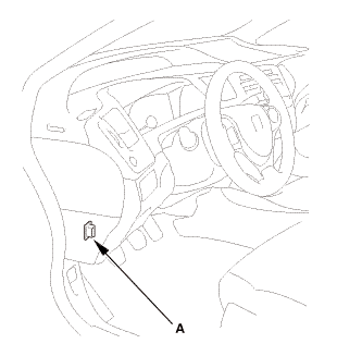
25. HDS DLC - Connection


1.

Connect the HDS to the data link connector (DLC) (A) located under the driver's side of the dashboard.


2.

Turn the ignition switch to ON (II).


3.

Make sure the HDS communicates with the vehicle. If it does not communicate, go to the DLC circuit troubleshooting.


26. VSA Sensor Neutral Position - Memorization

1.

Park the vehicle on a flat and level surface, with the steering wheel in the straight ahead position.


2.

Select VSA ADJUSTMENT, then select ALL SENSORS with the HDS, and follow the screen prompts.


NOTE: See the HDS Help menu for specific instructions.


27. Steering Angle Sensor Neutral Position - Clear

1.

Select EPS ADJUSTMENT, then select EPS STEERING ANGLE SENSOR VALUE CLEAR and follow the screen prompts on the HDS.


NOTE: See the HDS Help menu for specific instructions.


28. Maintenance Minder Reset

1.

After doing all procedures, select the individual maintenance item you wish to reset with the HDS..


Engine Oil Jet and Bolt Inspection (R18Z1)
Removal 1. Intake Manifold and Throttle Body Assembly 1. Remove the intake air duct. ...

Engine Oil Replacement
1. Warm Up The Engine 1. Warm up the engine. 2. Vehicle Lift ...

See also:

Honda Civic Owners Manual. Using Automatic Heating
The automatic heating system maintains the interior temperature you select. The system also selects the proper mix of heated or cooled air that raises or lowers the interior temperature to your preference as quickly as possible. Use the system when the engine is running. 1. Press the A ...

© 2016-2024 Copyright www.hocivic.com

0.0076