Honda Civic manuals

Honda Civic Service Manual: Engine Oil Jet and Bolt Inspection (R18Z1)

Honda Civic Service Manual / Powertrain / Engine / Engine Lubrication / Engine Oil Jet and Bolt Inspection (R18Z1)

Removal

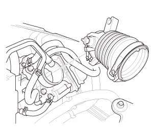
1. Intake Manifold and Throttle Body Assembly

1.

Remove the intake air duct.


2.

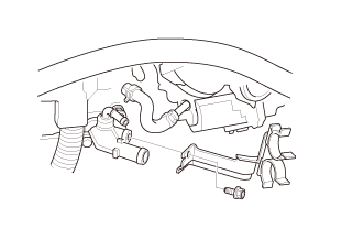
Remove the heater hose clamp bracket.


3.

Disconnect the water bypass hoses (A).


4.

Disconnect the PCV hose (B).


5.

Disconnect the connectors (C).


6.

Remove the harness clamps (D).


7.

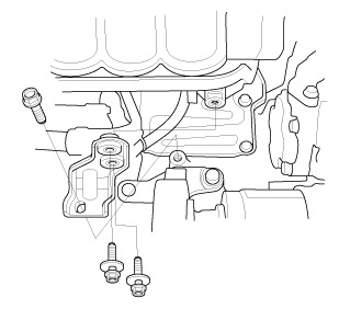
Remove the intake manifold bracket.


8.

Remove the intake manifold and throttle body assembly from the cylinder head.


2. Engine Wire Harness

1.

Remove the engine wire harness.


3. Manual Transmission Assembly (M/T)

1.

Remove the manual transmission.


4. Pressure Plate


1.

Install the ring gear holder.


2.

Install the clutch alignment shaft and the remover handle.


3.

To prevent warping, loosen the pressure plate mounting bolts (A) in a crisscross pattern in several steps.


4.

Remove the pressure plate (B).


5. Clutch Disc

1.

Remove the clutch disc (A), the clutch alignment shaft, and the remover handle.


6. Flywheel

n7lab-wnolun


1.

Remove the flywheel (A).


NOTE: Loosen the flywheel mounting bolts (B) in a crisscross pattern in several steps.


2.

Remove the ring gear holder.


7. Automatic Transmission Assembly (A/T)

1.

Remove the automatic transmission.


8. Drive Plate Assembly

1.

Remove the drive plate (A) and the washer (B).


9. A/F Sensor (Sensor 1)


1.

Disconnect the connector.


2.

Remove the A/F sensor (A).


10. Exhaust Chamber Cover

1.

Remove the exhaust chamber cover (A).


11. Catalytic Converter and EGR Pipe Assembly

1.

Remove the EGR pipe.


2.

Remove the catalytic converter.


12. Thermostat Housing

1.

Remove the thermostat housing.


13. Alternator

1.

Remove the alternator.


14. Lower Torque Rod Bracket (M/T)

1.

Remove the lower torque rod bracket.


15. Lower Torque Rod Bracket (A/T)

1.

Remove the lower torque rod bracket.


16. Intermediate Shaft Assembly

1.

Remove the crankshaft position (CKP) sensor cover (A).


2.

Remove the intermediate shaft (A) from the differential.


NOTE: Hold the intermediate shaft horizontal until it is clear of the differential to prevent damaging the oil seal (B).


17. A/C Compressor Bracket

1.

Remove the A/C compressor bracket.


18. Water Pump Pulley

1.

Remove the water pump pulley.


19. Auto Tensioner Assembly


1.

Remove the drive belt auto-tensioner (A).


2.

Check for oil leaks from the drive belt auto-tensioner damper (B) and check for damage to the damper rubber.


20. Cylinder Head Cover and/or Packing


1.

Remove the dipstick (A).


2.

Disconnect the breather hose (B).


3.

Remove the cylinder head cover.


21. Check The No.1 Piston at Top Dead Center (With Cam Chain Case/Oil Pump)

1.

Set the No. 1 piston at top dead center (TDC). The ‘‘UP’’ mark (A) on the camshaft sprocket should be at the top, and the TDC grooves (B) on the camshaft sprocket should line up with the top edge of the head.


22. Crankshaft Pulley

[av


1.

Hold the pulley with the holder handle (A) and the crankshaft pulley holder (B).


2.

Remove the bolt with a socket, 19 mm (C) and a breaker bar.


3.

Remove the crankshaft pulley.


23. Engine Oil Pump Assembly

1.

Disconnect the PCV hose.


2.

Remove the oil pump.


24. Cam Chain Auto-Tensioner

1.

Measure the tensioner rod length between the tensioner body and bottom of the flat surface section on the tensioner rod. If the length is more than the service limit, replace the cam chain.


Tensioner Rod Length

Service Limit:

14.5 mm (0.571 in)


2.

Loosely install the crankshaft pulley.


3.

Turn the crankshaft counterclockwise to compress the auto-tensioner.


4.

Rotate the crankshaft counterclockwise to align the holes on the lock (A) and the auto-tensioner (B).


5.

Insert a 1.0 mm (1/32 in) diameter pin (C) into the holes.


6.

Turn the crankshaft clockwise to secure the pin.


NOTE: If the holes in the lock and the auto-tensioner do not align, continue to rotating the crankshaft counterclockwise until the holes align, then install the pin.


7.

Remove the cam chain auto-tensioner.


8.

Remove the crankshaft pulley.


25. Cam Chain


1.

Remove the cam chain guide (A) and the cam chain tensioner arm (B).


2.

Remove the cam chain.


26. Oil Pan Assembly

1.

Using a flat blade screwdriver, separate the oil pan from the lower block in the places shown.


2.

Remove the oil pan.


27. Engine Oil Strainer

1.

Remove the oil strainer.


28. Engine Baffle Plate

1.

Remove the baffle plate.


29. Cylinder Lower Block Assembly

1.

Remove the 8 mm bolts in the sequence shown.


2.

Remove the bearing cap bolts. To prevent warpage, loosen the bolts in sequence 1/3 turn at a time; repeat the sequence until all bolts are loosened.


3.

Using a flat blade screwdriver, separate the lower block from the engine block in the places shown.


4.

Remove the lower block and the bearings. Keep all the bearings in order.


30. Crankshaft


1.

Lift the crankshaft (A) out of the engine block.


2.

Remove the thrust washers (B).


31. Engine Oil Jet

1.

Remove the oil jet bolts (A) and the oil jets (B).


Inspection

1. Engine Oil Jet and Bolt - Inspection

in!

1.

Inspect the oil jet and bolt as follows.


Make sure that a 1.1 mm (1/32 in) diameter drill bit will go through the nozzle hole (A) (1.2 mm (0.047 in) diameter).

Insert the other end of a 0.9 mm (1/32 in) drill bit into the oil intake (1.0 mm (0.039 in) diameter). Make sure the check ball (B) moves smoothly and has a stroke of about 4.0 mm (0.157 in).

Check the oil jet operation with an air nozzle. It should take at least 310 kPa (3.2 kgf/cm2, 46 psi) to unseat the check ball.


Installation

1. Engine Oil Jet

u.75mm


1.

Carefully install the oil jets (A).


2.

Tighten the oil jet bolts (B).


2. Crankshaft

1.

Hold the crankshaft so rod journal No. 2 and rod journal No. 3 are straight up, then lower the crankshaft into the engine block.


NOTE: Be careful not to damage the journals and the CKP pulse plate.


2.

Apply new engine oil to the thrust washer surfaces. Install the thrust washers in the No. 4 journal of the engine block.


3. Cylinder Lower Block Assembly


1.

Remove all of the old liquid gasket from the lower block mating surfaces, the bolts, and the bolt holes.


2.

Clean and dry the lower block mating surfaces.


3.

Apply liquid gasket, (P/N 08718-0004 or 08718-0009) to the engine block mating surface of the lower block, and to the inside edge of the threaded bolt holes. Install the component within 5 minutes of applying the liquid gasket.


NOTE:

Apply a 2.5 mm (0.098 in) diameter bead of liquid gasket along the broken line (A).

If too much time has passed after applying the liquid gasket, remove the old liquid gasket and residue, then reapply new liquid gasket.


4.

Put the lower block on the engine block.


5.

Apply new engine oil to the threads and flange of the bearing cap bolts.


6.

Torque the bearing cap bolts, in sequence, to 25 N·m (2.5 kgf·m, 18 lbf·ft).


7.

Tighten the bearing cap bolts an additional 57 °.


8.

Torque the 8 mm bolts, in sequence, to 24 N·m (2.4 kgf·m, 17 lbf·ft).


NOTE:

Wait at least 30 minutes before filling the engine with oil.

Do not run the engine for at least 3 hours after installing the lower block.


4. Engine Baffle Plate

1.

Install the baffle plate.


5. Engine Oil Strainer

1.

Install the oil strainer (A) with new O-ring (B).


6. Oil Pan Assembly

mm


1.

Remove all of the old liquid gasket from the oil pan mating surfaces, the bolts, and the bolt holes.


2.

Clean and dry the oil pan mating surfaces.


3.

Apply liquid gasket, (P/N 08718-0004 or 08718-0009) to the engine block mating surface of the oil pan, and to the inside edge of the threaded bolt holes. Install the component within 5 minutes of applying the liquid gasket.


NOTE:

Apply a 2.5 mm (0.098 in) diameter bead of liquid gasket along the broken line (A).

If too much time has passed after applying the liquid gasket, remove the old liquid gasket and residue, then reapply new liquid gasket.


4.

Install the dowel pins (A).


5.

Install the oil pan (B) with new O-rings (C).


6.

Tighten the bolts in three steps. In the final step, torque all bolts, in sequence, to 18 N·m (1.8 kgf·m, 13 lbf·ft). Wipe off the excess liquid gasket on the each side of crankshaft pulley and flywheel/drive plate.


NOTE:

Wait at least 30 minutes before filling the engine with oil.

Do not run the engine within 3 hours after installing the oil pan.


7. Cam Chain

1.

Install the cam chain on the crankshaft sprocket with the colored piece (A) aligned with the mark (B) on the crankshaft sprocket.


2.

Install the cam chain on the camshaft sprocket with the colored link plate (A) aligned with the mark (B) on the camshaft sprocket.


...,is(1.2

3.

Install the cam chain guide (A) and the cam chain tensioner arm (B).


8. Cam Chain Auto-Tensioner

1.

Compress the cam chain auto-tensioner when replacing the cam chain. Remove the pin (A) from the auto-tensioner that was installed during removal. Turn the plate (B) counterclockwise, to release the lock, then press the rod (C), and set the first cam (D) to the first edge of the rack (E). Insert the 1.0 mm (1/32 in) diameter pin back into the holes (F).


NOTE: If the chain tensioner is not set up as described, the tensioner will be damaged.


nokvf-in.

2.

Install the cam chain auto-tensioner.


3.

Remove the pin from the cam chain auto-tensioner.


9. Engine Oil Pump Assembly


1.

Check the oil pump oil seal for damage. If the oil seal is damaged, replace the oil seal.


2.

Remove all of the old liquid gasket from the oil pump mating surfaces, the bolts, and the bolt holes.


3.

Clean and dry the oil pump mating surfaces.


4.

Apply liquid gasket (P/N 08718-0004 or 08718-0009) to the engine block mating surface of the oil pump, and to the inside edge of the threaded bolt holes. Install the component within 5 minutes of applying the liquid gasket.


NOTE:

Apply a 2.5 mm (0.098 in) diameter bead of liquid gasket along the broken line (A), (B), and (C).

If too much time has passed after applying the liquid gasket, remove the old liquid gasket and residue, then reapply new liquid gasket.


5.

Apply liquid gasket (P/N 08718-0004 or 08718-0009) to the oil pan mating surface of the oil pump, and to the inside edge of the threaded bolt holes. Install the component within 5 minutes of applying the liquid gasket.


Apply a 2.5 mm (0.098 in) diameter bead of liquid gasket along the broken line (A).

If too much time has passed after applying the liquid gasket, remove the old liquid gasket and residue, then reapply new liquid gasket.


25mm(7(32k1n1omm12


6.

Set the edge of the oil pump (A) on the edge of the oil pan (B) with new O-rings (C).


7.

Install the oil pump on the engine block (D).


8.

Loosely install the dowel bolts (E), then tighten the 8mmbolts (F), the 6 mm bolts (G) and the dowel bolts.


9.

Wipe off the excess liquid gasket on the oil pan and oil pump mating surface.


NOTE:

When installing the oil pump, do not slide the bottom surface onto the oil pan mounting surface.

Wait at least 30 minutes before filling the engine with oil.

Do not run the engine within 3 hours after installing the oil pump.


10. Crankshaft Oil Seal, Transmission side


1.

Apply a light coat of new engine oil to the crankshaft and the lip of the crankshaft oil seal.


2.

Use the driver handle and the oil seal driver attachment, 96 mm to drive a new crankshaft oil seal (A) squarely into the engine block to the specified installed height.


3.

Measure the distance between the engine block (A) and the crankshaft oil seal (B).


Oil Seal Installed Height:

0.2-1.2 mm (0.008-0.047 in)


11. Crankshaft Pulley


1.

Clean the crankshaft pulley (A), the crankshaft (B), the bolt (C), and the washer (D).


2.

Lubricate with new engine oil as shown.


3.

Install the crankshaft pulley (A) onto the crankshaft (B) by aligning the flat sides (C) of the pulley with the flat sides (D) of the inner oil pump gear.


o7jaanmo2oa


When a new crankshaft or a new pulley bolt is installed


4.

Hold the pulley with the holder handle (A) and crankshaft pulley holder (B), torque the bolt to 180 N·m (18.4 kgf·m, 133 lbf·ft) with a torque wrench and a socket (C), then remove the bolt.


5.

Torque the bolt to 50 N·m (5.1 kgf·m, 37 lbf·ft) with a torque wrench and a socket.


NOTE: Tighten the crankshaft pulley bolt. Do not use an impact wrench.


6.

Tighten the bolt an additional 82 °.


o7jaanmo2oa


When the crankshaft or the pulley bolt is reused


7.

Hold the pulley with the holder handle (A) and crankshaft pulley holder (B), then torque the bolt to 70 N·m (7.1 kgf·m, 52 lbf·ft) with a torque wrench and a socket (C).


NOTE: Tighten the crankshaft pulley bolt. Do not use an impact wrench.


8.

Tighten the bolt an additional 90 °.


12. Cylinder Head Cover and/or Packing


1.

Thoroughly clean the head cover gasket and the groove.


NOTE: Check and, if necessary, replace the head cover gasket.


2.

Install the head cover gasket (A) in the groove of the cylinder head cover (B).


3.

Make sure the head cover gasket is seated securely.


4.

Clean the head cover contacting surfaces with a shop towel.


5.

Remove the old liquid gasket from the top edge matting surfaces of the oil pump (A) and cylinder head (B).


6.

Apply liquid gasket (P/N 08718-0004 or 08718-0009) to the chain case contact areas. Install the component within 5 minutes of applying the liquid gasket.


NOTE:

Apply a 5 mm (0.20 in) diameter bead of liquid gasket to the mating surfaces (C).

If too much time has passed after applying the liquid gasket, remove the old liquid gasket and residue, then reapply new liquid gasket.


7.

Install the cylinder head cover.


8.

Tighten the bolts in two steps. In the final step, torque all bolts in sequence to 10 N·m (1.0 kgf·m, 7 lbf·ft).


NOTE:

Wait at least 30 minutes before filling the engine with oil.

Do not run the engine for at least 3 hours after installing the head cover.


9.

Connect the breather hose (A).


10.

Install the dipstick (B).


13. Auto Tensioner Assembly

inl.25mmssn-m

1.

Install the drive belt auto-tensioner.


14. Water Pump Pulley

1.

Install the water pump pulley.


15. A/C Compressor Bracket

1.

Install the A/C compressor bracket.


16. Intermediate Shaft Assembly

inmmn-mu.o

1.

Insert the intermediate shaft (A) into the differential correctly.


NOTE: Insert the intermediate shaft carefully to prevent damaging the oil seal (B).


mms.

2.

Install the crankshaft position (CKP) sensor cover (A).


17. Lower Torque Rod Bracket (M/T)

mm

1.

Install the lower torque rod bracket.


18. Lower Torque Rod Bracket (A/T)

u.z5mm75n-mmm

1.

Install the lower torque rod bracket.


19. Alternator

1.

Install the alternator.


20. Thermostat Housing

11

1.

Install the thermostat housing (A), using a new gasket (B) and new O-ring (C).


21. Catalytic Converter and EGR Pipe Assembly

num(2.2m.2:m41!

1.

Install the catalytic converter.


22n-m

2.

Install the EGR pipe.


22. Exhaust Chamber Cover

1.

Install the exhaust chamber cover (A).


23. A/F Sensor (Sensor 1)


1.

Install the A/F sensor (A).


2.

Connect the connector.


24. Drive Plate Assembly

55

1.

Install the drive plate (A) and the washer (B), and tighten the eight bolts in a crisscross pattern in at least two steps.


25. Automatic Transmission Assembly (A/T)

usmmn-mlbml)

1.

Install the automatic transmission.


26. Flywheel


1.

Install the flywheel (A) on the crankshaft, and install the mounting bolts (B) finger-tight.


2.

Install the ring gear holder.


:2minn-inno

3.

Tighten the flywheel mounting bolts (A) in a crisscross pattern in several steps.


27. Clutch Disc

(pm


1.

Temporarily install the clutch disc onto the splines of the transmission mainshaft. Make sure the clutch disc slides freely on the mainshaft.


2.

Apply super high temp urea grease (P/N 08798-9002) to the splines (A) of the clutch disc (B).


NOTE: Wipe off any excess grease.


3.

Install the clutch disc using the clutch alignment shaft and the remover handle.


28. Pressure Plate

1.

Install the pressure plate (A) and the mounting bolts (B) finger-tight.


a7aag-suaa1aa


2.

Torque the pressure plate mounting bolts (A) in a crisscross pattern.


NOTE:

Tighten the bolts in several steps to prevent warping the diaphragm spring.

Make sure that there is no clearance between the pressure plate and the flywheel.


Specified Torque:

25 N·m (2.5 kgf·m, 18 lbf·ft)


3.

Remove the ring gear holder.


4.

Remove the clutch alignment shaft and the remover handle.


5.

Make sure the diaphragm spring fingers are all the same height.


29. Manual Transmission Assembly (M/T)

1.

Install the manual transmission.


30. Engine Wire Harness

1.

Install the engine wire harness.


31. Intake Manifold and Throttle Body Assembly


1.

Install the intake manifold and throttle body assembly (A) with new gaskets (B).


2.

Tighten the bolts and nuts in a crisscross pattern in three steps, beginning with the inner bolt.


3.

Install the intake manifold bracket.


4.

Connect the PCV hose (A).


5.

Connect the connectors (B).


6.

Install the harness clamps (C).


7.

Connect the water bypass hoses (D).


8.

Install the heater hose clamp bracket.


9.

Install the intake air duct.


Engine Oil Jet and Bolt Inspection (R18A9)
Removal 1. Intake Manifold and Throttle Body Assembly (Natural Gas Model) 1. Remove the intake air duct. ...

Engine Oil Pan Removal and Installation (K24Z7)
1111Q1 1. Warm Up The Engine 1. Warm up the engine. 2. Upper Torque Rod Mounting Bol ...

See also:

Honda Civic Owners Manual. Types of Airbags
Your vehicle is equipped with three types of airbags: Front airbags: Airbags in front of the driver’s and front passenger’s seats. Side airbags: Airbags in the driver’s and front passenger’s seat-backs. Side curtain airbags: Airbags above the side windows. Each is discussed in ...

© 2016-2024 Copyright www.hocivic.com

0.0073