Honda Civic Service Manual: Side Impact Sensor (First) Removal and Installation (2-door)
7521B6 LEFT FRONT
7521B7 RIGHT FRONT

Removal
|
NOTE: SRS components are located in this area. Review the SRS
component locations and the precautions and procedures before doing
repairs or service.
|
| 1. |
Battery Terminal (SRS) - Disconnection |
|
|
|
1.
|
Make sure the ignition switch is in LOCK (0).
|
|
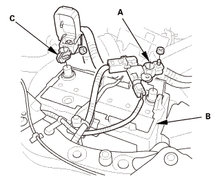
2.
|
Disconnect and isolate the negative cable and battery
sensor (A) from the battery (B).
|
|
NOTE: Always disconnect the negative side first.
|
|
3.
|
Disconnect the positive cable (C) from the battery.
|
|
4.
|
Wait at least 3 minutes before starting work.
|
|
|
|
|
1.
|
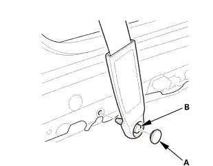
Driver's side: Remove the lower anchor cap (A).
|
|
2.
|
Driver's side: Remove the lower anchor bolt (B).
|
|
|

|
|
3.
|
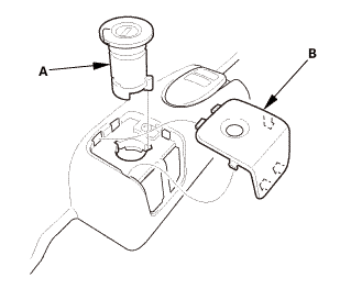
Driver's side: Remove the cap (A).
|
|
4.
|
Driver's side: Remove the opener lock cylinder (B).
|
|
|
|
|
5.
|
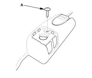
Driver's side: Remove the screw (A).
|
|
|
Driver's side
Passenger's side
|
|
6.
|
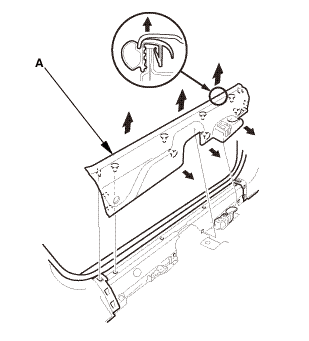
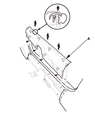
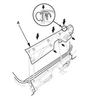
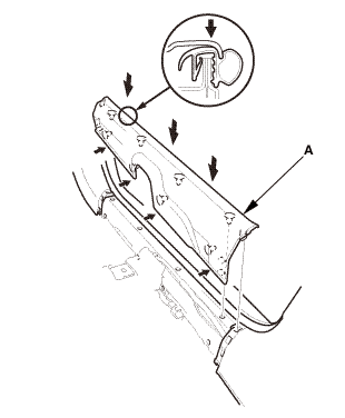
Remove the front door sill trim (A).
|
|
| 3. |
Side Impact Sensor (First) |
|
|
|
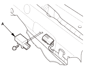
1.
|
Disconnect the side impact sensor (first) connector on
the floor wire harness.
|
|
2.
|
Remove the TORX bolt using a TORX T30 bit, then remove
the side impact sensor (first) (A).
|
|

Installation
|
NOTE: SRS components are located in this area. Review the SRS
component locations and the precautions and procedures before doing
repairs or service.
|
| 1. |
Side Impact Sensor (First) |
|
|
|
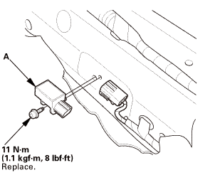
1.
|
Install the side impact sensor (first) (A) with the new
TORX bolt using a TORX T30 bit.
|
|
2.
|
Connect the side impact sensor (first) connector on the
floor wire harness.
|
|
| 2. |
Battery Terminal (SRS) - Reconnection |
|
 (o.2ao.sam. (o.2ao.sam.
|
|
NOTE: If the battery performs abnormally, test the battery.
|
|
1.
|
Clean the battery terminals.
|
|
2.
|
Connect the positive cable (A) to the battery (B).
|
|
NOTE: Always connect the positive side first.
|
|
3.
|
Connect the negative cable and battery sensor (C) to
the battery.
|
|
4.
|
Apply multipurpose grease to the terminals to prevent
corrosion.
|
|
|
|
|
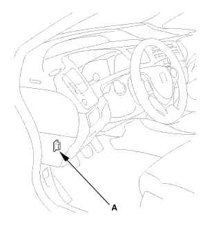
1.
|
Connect the HDS to the data link connector (DLC) (A)
located under the driver's side of the dashboard.
|
|
2.
|
Turn the ignition switch to ON (II).
|
|
3.
|
Make sure the HDS communicates with the vehicle. If it
does not communicate, go to the DLC circuit troubleshooting.
|
|
|
|
1.
|
Clear the DTC(s) by following the screen prompts on the
HDS.
|
|
2.
|
Turn the ignition switch to LOCK (0), then wait for 10
seconds.
|
|
| 5. |
Confirm Proper SRS Operation |
|
|
Turn the ignition switch to ON (II), and check that the
SRS indicator comes on for about 6 seconds and then goes
off.
|
|
|
Driver's side
Passenger's side
|
|
1.
|
Install the front door sill trim (A).
|
|
|

|
|
2.
|
Driver's side: Install the screw (A).
|
|
|
|
|
3.
|
Driver's side: Install the opener lock cylinder (A).
|
|
4.
|
Driver's side: Install the cap (B).
|
|
|
 @@@ @@@
|
|
5.
|
Driver's side: Assemble the washer, the collar, and the
bushing on the lower anchor bolt as shown.
|
|
NOTE: Apply medium strength liquid thread lock to the
lower anchor bolt before reinstallation.
|
|
|
 7/1s-2om-min 7/1s-2om-min
|
|
6.
|
Driver's side: Install the lower anchor bolt (A).
|
|
7.
|
Driver's side: Install the lower anchor cap (B).
|
|
7521A5 LEFT
7521C2 RIGHT
7521C9 BOTH
Removal
NOTE:
SRS ...
7521B6 LEFT FRONT
7521B7 RIGHT FRONT
NOTE: SRS components are located in this area. Review the SRS
component locations and the precautions and procedures be ...
 Side Curtain Airbag Removal and Installation (2-door)
 Side Impact Sensor (First) Removal and Installation (4-door)