Honda Civic Service Manual: Side Impact Sensor (First) Removal and Installation (4-door)
7521B6 LEFT FRONT
7521B7 RIGHT FRONT

|
NOTE: SRS components are located in this area. Review the SRS component
locations and the precautions and procedures before doing repairs or service.
|
| 1. |
Battery Terminal (SRS) - Disconnection |
|

|
|
1.
|
Make sure the ignition switch is in LOCK (0).
|
|
2.
|
Disconnect and isolate the negative cable with the battery sensor
(A) from the battery.
|
|
NOTE:
|
|

|
Always disconnect the negative side first.
|
|
|
|
To protect the battery sensor connector (B) from
damage, do not hold it when removing the negative
terminal.
|
|
|
|
Do not disconnect the battery sensor from the
negative terminal (C).
|
|
|
|
3.
|
Disconnect the positive cable (D) from the battery.
|
|
4.
|
Wait at least 3 minutes before starting work.
|
|
|

|
|
1.
|
Driver's side: Remove the cap (A) from the front door sill trim
(B).
|
|
2.
|
Driver's side: Remove the opener lock cylinder (C).
|
|
|
|
|
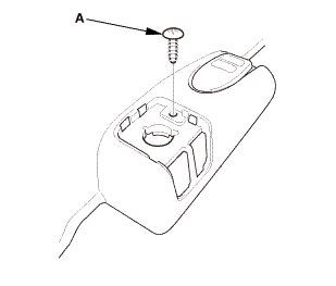
3.
|
Driver's side: Remove the screw (A).
|
|
|
Driver's side

Passenger's side

|
|
4.
|
Remove the front door sill trim (A).
|
|
|

|
|
1.
|
While pushing down on the rear seat cushion (A), pull the seat
hook handle (B) to release the hook (C).
|
|
2.
|
While pulling up the seat cushion, remove the rear door sill
trim (D).
|
|
| 4. |
Front and Rear Door Opening Seals as Needed |
|
Front

Rear

|
|
1.
|
Remove the front door opening seal (A) and the rear door opening
seal (B) as needed.
|
|
|

|
|
1.
|
Slide the front seat forward fully.
|
|
2.
|
13-14 Models (driver's side): Remove the B-pillar lower cover
(A).
|
|
|
12 Model

13-14 Models

|
|
3.
|
Remove the B-pillar lower trim (A).
|
|
| 6. |
Side Impact Sensor (First) |
|

|
|
1.
|
Disconnect the side impact sensor (first) connector on the floor
wire harness.
|
|
2.
|
Remove the TORX bolt using a TORX T30 bit, then remove the side
impact sensor (first) (A).
|
|

|
NOTE: SRS components are located in this area. Review the SRS component
locations and the precautions and procedures before doing repairs or service.
|
| 1. |
Side Impact Sensor (First) |
|

|
|
1.
|
Install the side impact sensor (first) (A) with the new TORX
bolt using a TORX T30 bit.
|
|
2.
|
Connect the side impact sensor (first) connector on the floor
wire harness.
|
|
| 2. |
Battery Terminal (SRS) - Reconnection |
|
 (o.2ao.sam. (o.2ao.sam.
|
|
NOTE: If the battery performs abnormally, test the battery.
|
|
1.
|
Clean the battery terminals.
|
|
2.
|
Connect the positive cable (A) to the battery.
|
|
NOTE: Always connect the positive side first.
|
|
3.
|
Connect the negative cable and the battery sensor (B) to the
battery.
|
|
NOTE: To protect the battery sensor connector (C) from damage,
do not hold it when installing the negative terminal.
|
|
4.
|
Apply multipurpose grease to the terminals to prevent corrosion.
|
|
|
|
|
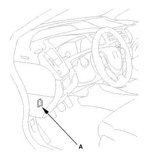
1.
|
Connect the HDS to the data link connector (DLC) (A) located
under the driver's side of the dashboard.
|
|
2.
|
Turn the ignition switch to ON (II).
|
|
3.
|
Make sure the HDS communicates with the vehicle. If it does not
communicate, go to the DLC circuit troubleshooting.
|
|
|
|
1.
|
Clear the DTC(s) by following the screen prompts on the HDS.
|
|
2.
|
Turn the ignition switch to LOCK (0), then wait for 10 seconds.
|
|
| 5. |
Confirm Proper SRS Operation |
|
|
Turn the ignition switch to ON (II), and check that the SRS indicator
comes on for about 6 seconds and then goes off.
|
|
|
12 Model

13-14 Models
|
|
1.
|
Install the B-pillar lower trim (A).
|
|
|
|
|
2.
|
13-14 Models (driver's side): Install the B-pillar lower cover
(A).
|
|
| 7. |
Front and Rear Door Opening Seals as Needed |
|
Front

Rear

|
|
1.
|
Install the front door opening seal (A) and the rear door opening
seal (B).
|
|
|

|
|
1.
|
While pulling up the rear seat cushion (A), install the rear
door sill trim (B).
|
|
2.
|
Push down the seat cushion, then install the hook (C) to the
rear seat cushion clip (D).
|
|
|
Driver's side

Passenger's side

|
|
1.
|
Install the front door sill trim (A).
|
|
|

|
|
2.
|
Driver's side: Install the screw (A).
|
|
|

|
|
3.
|
Driver's side: Install the opener lock cylinder (A).
|
|
4.
|
Driver's side: Install the cap (B) to the front door sill trim
(C).
|
|
7521B6 LEFT FRONT
7521B7 RIGHT FRONT
Removal
NOTE: SRS components are located in this area. Review the SRS component
locations and the precautions and procedures before doing re ...
7521C3 LEFT REAR
7521C4 RIGHT REAR
Removal
NOTE: SRS components are located in this area. Review the SRS component
locations and the precautions and procedures before doing repa ...
See also:
Honda Civic Owners Manual. Apple CarPlay Menu
Phone
Access the contact list, make phone calls, or listen to voice mail.
Messages
Check and reply to text messages, or have messages read to you.
Music
Play music stored on your iPhone.
Apple CarPlay
Only iPhone 5 or newer versions with iOS 8.4 or later
are compatible with Apple CarPlay ...
 Side Impact Sensor (First) Removal and Installation (2-door)
 Side Impact Sensor (Second) Removal and Installation (2-door)