Honda Civic Service Manual: Moonroof Drain Tube Removal and Installation (4-door)

Removal
| 1. |
Battery Terminal (SRS) - Disconnection |
|
|
|
1.
|
Make sure the ignition switch is in LOCK (0).
|
|
2.
|
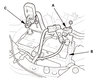
Disconnect and isolate the negative cable and battery sensor
(A) from the battery (B).
|
|
NOTE: Always disconnect the negative side first.
|
|
3.
|
Disconnect the positive cable (C) from the battery.
|
|
4.
|
Wait at least 3 minutes before starting work.
|
|
|

|
|
1.
|
Pull out the A-pillar trim (A) to release the clips.
|
|
|

|
|
2.
|
Put a shop towel (A) in the opening between the A-pillar trim
(B) and the dashboard to prevent dropping the A-pillar clips.
|
|
|

|
|
3.
|
Disconnect the connector (A), then remove the A-pillar trim (B).
|
|
NOTE: The upper clip (C) will stay in the body.
|
|
|

|
|
4.
|
Remove the upper clip (A) from the body.
|
|
5.
|
Repeat on the opposite side.
|
|
| 3. |
Front Door Opening Seal As Needed Both |
|

|
|
1.
|
Remove front door opening seal (A) as needed.
|
|
2.
|
Repeat on the opposite side.
|
|
|
 llghr llghr
|
|
1.
|
Turn the ceiling light switch OFF.
|
|
2.
|
Carefully pry off the lens (A).
|
|
3.
|
Remove the ceiling light (B).
|
|
4.
|
Disconnect the connector.
|
|
| 5. |
Both Front Door Sill Trims |
|

|
|
1.
|
Driver's side: Remove the cap (A) from the front door sill trim
(B).
|
|
2.
|
Driver's side: Remove the opener lock cylinder (C).
|
|
|
|
|
3.
|
Driver's side: Remove the screw (A).
|
|
|
Driver's side

Passenger's side

|
|
4.
|
Remove both front door sill trims (A).
|
|
| 6. |
Both Rear Door Sill Trims |
|

|
|
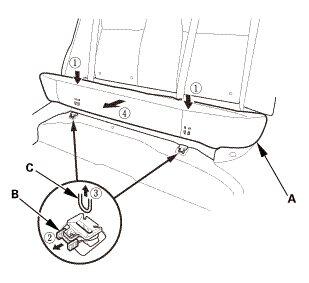
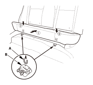
1.
|
While pushing down on the rear seat cushion (A), pull the seat
hook handle (B) to release the hook (C).
|
|
2.
|
While pulling up the seat cushion, remove the rear door sill
trim (D).
|
|
3.
|
The left side is shown; repeat on the right side.
|
|
| 7. |
Both Rear Door Opening Seals as Needed |
|

|
|
1.
|
Remove the rear door opening seal (A) as needed.
|
|
2.
|
The left side is shown; repeat on the right side.
|
|
| 8. |
Both B-Pillar Lower Trims |
|

|
|
1.
|
Slide the front seat forward fully.
|
|
2.
|
Remove the B-pillar lower trim (A).
|
|
3.
|
The left side is shown; repeat on the right side.
|
|
| 9. |
Both Front Seat Belt Lower Anchor Bolts |
|

|
|
1.
|
Remove the anchor cover (A).
|
|
2.
|
The driver's seat is shown; repeat on the passenger's seat.
|
|
|

|
|
3.
|
Remove the lower anchor bolt (A).
|
|
4.
|
The driver's seat is shown; repeat on the passenger's seat.
|
|
| 10. |
Both B-Pillar Upper Trims |
|

|
|
1.
|
Remove the bottom area of the B-pillar upper trim (A).
|
|
2.
|
The left side is shown; repeat on the right side.
|
|
|

|
|
3.
|
Remove the upper area of the B-pillar upper trim (A).
|
|
4.
|
The left side is shown; repeat on the right side.
|
|
|

|
|
5.
|
Pass the front seat belt lower anchor (A) out through the hole
in the slider (B), then remove the B-pillar upper trim (C).
|
|
6.
|
The left side is shown; repeat on the right side.
|
|
|
|
|
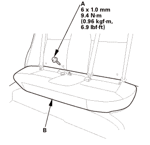
1.
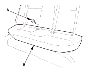
|
Remove the bolt (A) securing the rear seat cushion (B).
|
|
|
|
|
2.
|
While pushing down the rear seat cushion (A), pull the seat hook
handles (B) to release the hooks (C).
|
|
3.
|
Remove the rear seat cushion.
|
|
| 12. |
Both Rear Seat Side Bolsters |
|

|
|
1.
|
Remove the bolt (A) securing the rear seat side bolster (B).
|
|
2.
|
The left side is shown; repeat on the right side.
|
|
|

|
|
3.
|
Remove the rear seat side bolster (A).
|
|
4.
|
The left side is shown; repeat on the right side.
|
|
|

|
|
1.
|
Pull out the C-pillar trim (A) to release the clips.
|
|
2.
|
Remove the C-pillar trim.
|
|
NOTE: The front clip (B) will stay in the body.
|
|
3.
|
The left side is shown; repeat on the right side.
|
|
|

|
|
4.
|
Remove the front clip (A).
|
|
5.
|
The left side is shown; repeat on the right side.
|
|
| 14. |
Grab Handles for One Vehicle |
|

|
|
1.
|
Lower the grab handle (A).
|
|
2.
|
Insert the tips of the push pin/grab rail cap pliers (B) into
the notch.
|
|
|

|
|
3.
|
Gently squeeze the handles of the push pin/grab rail cap pliers
(A), and pull the cap (B) straight out.
|
|
|

|
|
4.
|
Remove the grab handle (A).
|
|
|
Driver's side

Passenger's side

|
|
1.
|
Pull out both front door opening seals (A) as needed.
|
|
2.
|
Remove both kick panels (B).
|
|
|

|
|
1.
|
Push the hook (A) with a flat-tip screwdriver through the hole
in the front side of the bracket cover (B).
|
|
NOTE: Make sure the hook is unlocked.
|
|
|

|
|
2.
|
While pushing in the hook (A) with a flat-tip screwdriver, release
the sunvisor (B) from the holder (C), and rotate the sunvisor backward
45 °.
|
|
NOTE: Make sure the hook slides into the bracket cover as you
rotate the sunvisor.
|
|
|

|
|
3.
|
Disconnect the connector (A), then remove the sunvisor (B).
|
|
NOTE: If the sunvisor cannot be removed, the hook has not rotated
into the bracket cover. Repeat step 2 to rotate the hook.
|
|
|

|
|
4.
|
If necessary, turn the sunvisor holder (A) 45 ° counterclockwise,
then remove it from the holder grommet (B).
|
|
|

|
|
5.
|
If necessary, remove the holder grommet (A).
|
|
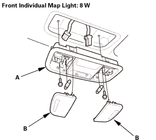
| 17. |
Front Individual Map Light (without moonroof) |
|
|
|
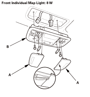
1.
|
Turn the front individual map light switch OFF.
|
|
2.
|
Carefully pry off the lenses (A) with a flat-tip screwdriver.
|
|
3.
|
Disconnect the connector.
|
|
4.
|
Remove the front individual map light (B).
|
|
|
Except K24Z7 engine
|
|
1.
|
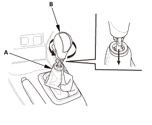
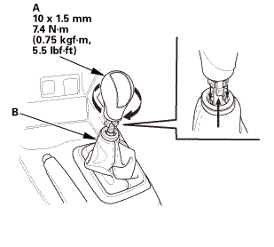
Except K24Z7 engine: Lower the shift lever boot (A) to release
the hooks from the boot.
|
|
2.
|
Except K24Z7 engine: Remove the shift lever knob (B).
|
|
|
K24Z7 engine
|
|
3.
|
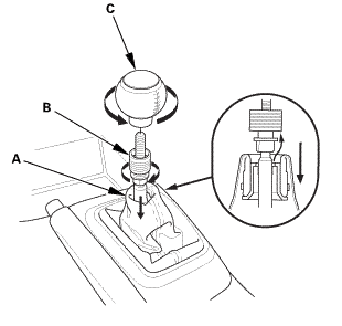
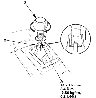
K24Z7 engine: Lower the shift lever boot (A) to release the hooks
from the boot.
|
|
4.
|
K24Z7 engine: Loosen the shift lever boot ring (B).
|
|
5.
|
K24Z7 engine: Remove the shift lever knob (C).
|
|
6.
|
K24Z7 engine: Remove the shift lever boot ring.
|
|
| 19. |
Center Console Panel Assembly (M/T) |
|
|
|
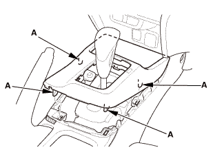
1.
|
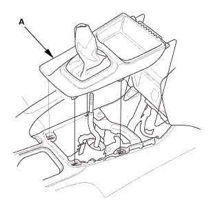
Remove the center console panel (A).
|
|
| 20. |
Center Console Panel Assembly (A/T) |
|
|
|
2.
|
Remove the center console panel (A).
|
|
| 21. |
Cup Holder Panel Assembly |
|
|
|
1.
|
Remove the cup holder panel assembly (A).
|
|
|
|
|
2.
|
Disconnect the connector (B).
|
|
|
|
|
3.
|
Remove the console box mat (A).
|
|
|
|
|
5.
|
Disconnect the connector (A).
|
|
|

|
|
6.
|
Remove the center console (A).
|
|
| 23. |
Center Console Bracket (M/T) |
|

|
|
1.
|
M/T: Remove the center console bracket (A).
|
|
|

|
|
1.
|
Without moonroof: From the driver's A-pillar, detach the harness
clips (A).
|
|
|

|
|
2.
|
Without moonroof: From under the driver's dash, disconnect the
connector (A), and detach the harness clips (B).
|
|
|

|
|
3.
|
From the passenger's A-pillar, disconnect the connector (A),
and detach the harness clips (B).
|
|
|

|
|
4.
|
For some models: Release the glove box stops (A) on each side
of the dashboard.
|
|
|

|
|
5.
|
For some models: From the glove box opening, disconnect the connector
(A), and detach the harness clip (B).
|
|
|

|
|
6.
|
From the right C-pillar, disconnect the connector (A), and detach
the harness clip (B).
|
|
|

|
|
7.
|
From the left C-pillar, disconnect the terminal (A), and remove
the bolt (B), then detach the harness clip (C).
|
|
|
M/T

A/T

|
|
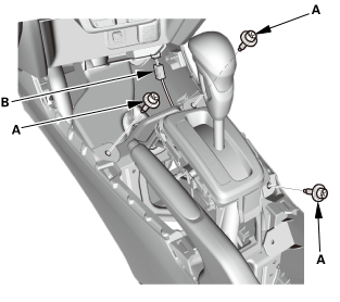
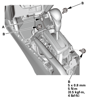
8.
|
Remove the bolts (A) securing the shift lever assembly (B).
|
|
9.
|
Lay the shift lever assembly down as needed.
|
|
|
Without moonroof

With moonroof

|
|
10.
|
Slide the front seat all the way back, and recline the seat-back
fully.
|
|
11.
|
With the help of an assistant, lower the headliner (A).
|
|
|

|
|
12.
|
With the help of an assistant, remove the headliner (A) through
the passenger's front door opening.
|
|
NOTE: Do not bend the headliner. Bending the headliner will crease
and damage it.
|
|
| 25. |
Moonroof Front Drain Tube Both |
|

|
|
1.
|
Disconnect the moonroof front drain tube (A).
|
|
2.
|
Pull out the moonroof front drain valve (B).
|
|
3.
|
Tie a string to the top end of the moonroof front drain tube,
then pull down the drain tube out of the A-pillar.
|
|
4.
|
Leave the string in the pillar to use when reinstalling the moonroof
front drain tube.
|
|
5.
|
Repeat on the opposite side.
|
|
|
|
|
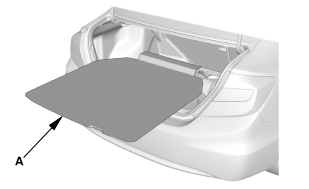
1.
|
Remove the trunk floor cover (A).
|
|
| 27. |
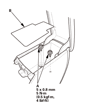
Trunk Lid Weatherstrip As Needed |
|

|
|
1.
|
Remove the trunk lid weatherstrip (A) as needed.
|
|
| 28. |
Trunk Rear Trim Panel |
|

|
|
1.
|
Remove the trunk rear trim panel (A).
|
|
| 29. |
Trunk Side Trim Panel Both |
|

|
|
1.
|
Remove the trunk side trim panel (A).
|
|
2.
|
Repeat on the opposite side.
|
|
| 30. |
Moonroof Rear Drain Tube Both |
|


|
|
1.
|
Disconnect the moonroof rear drain tube (A).
|
|
2.
|
Pull out the moonroof rear drain valve (B).
|
|
3.
|
Tie a string to the top end of the moonroof rear drain tube,
then pull down the drain tube out of the pillar.
|
|
4.
|
Leave the string in the pillar to use when reinstalling the moonroof
rear drain tube.
|
|
5.
|
Repeat on the opposite side.
|
|

Installation
| 1. |
Moonroof Rear Drain Tube Both |
|
|
|
1.
|
Tie the string that was left in the pillar to the top end of
the new moonroof rear drain tube (A) and pull it up into the roof.
|
|
2.
|
Connect the moonroof rear drain tube.
|
|
3.
|
Install the moonroof rear drain valve (B).
|
|
4.
|
Repeat on the opposite side.
|
|
| 2. |
Trunk Side Trim Panel Both |
|

|
|
1.
|
Install the trunk side trim panel (A).
|
|
2.
|
Repeat on the opposite side.
|
|
|

|
|
1.
|
Install the trunk rear trim panel (A).
|
|
| 4. |
Trunk Lid Weatherstrip as Needed |
|
|
|
1.
|
Install the trunk lid weatherstrip (A).
|
|
|
|
|
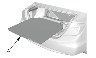
1.
|
Install the trunk floor cover (A).
|
|
| 6. |
Moonroof Front Drain Tube Both |
|
|
|
1.
|
Tie the string that was left in the A-pillar to the top end of
the new moonroof front drain tube (A) and pull it up into the roof.
|
|
2.
|
Connect the moonroof front drain tube.
|
|
3.
|
Install the moonroof front drain valve (B).
|
|
4.
|
Repeat on the opposite side.
|
|
|
|
|
1.
|
With the help of an assistant, take the headliner (A) in through
the passenger's front door opening.
|
|
NOTE: Do not bend the headliner. Bending the headliner will crease
and damage it.
|
|
|
Without moonroof
With moonroof
|
|
2.
|
With the help of an assistant, install the headliner (A).
|
|
|
M/T

A/T

|
|
3.
|
Install the bolts (A) securing the shift lever assembly (B).
|
|
|

|
|
4.
|
At the left C-pillar, connect the terminal (A), and install the
bolt (B), then install the harness clip (C).
|
|
|
|
|
5.
|
At the right C-pillar, connect the connector (A), and install
the harness clip (B).
|
|
|

|
|
6.
|
For some models: At the glove box opening, connect the connector
(A), and install the harness clip (B).
|
|
|

|
|
7.
|
For some models: Install the glove box stops (A) on each side
of the dashboard.
|
|
|

|
|
8.
|
At the passenger's A-pillar, connect the connector (A), and install
the harness clips (B).
|
|
|

|
|
9.
|
Without moonroof: Under the driver's dash, connect the connector
(A), and install the harness clips (B).
|
|
|

|
|
10.
|
Without moonroof: At the driver's A-pillar, install the harness
clips (A).
|
|
| 8. |
Center Console Bracket (M/T) |
|

|
|
1.
|
M/T: Install the center console bracket (A).
|
|
|

|
|
1.
|
Install the center console (A).
|
|
|
|
|
2.
|
Connect the connector (A).
|
|
|
|
|
3.
|
Install the bolts (A).
|
|
4.
|
Install the console box mat (B).
|
|
|
|
|
5.
|
Connect the connector (A).
|
|
6.
|
Install the bolts (B).
|
|
| 10. |
Cup Holder Panel Assembly |
|
|
|
1.
|
Install the cup holder panel assembly (A).
|
|
| 11. |
Center Console Panel Assembly (A/T) |
|

|
|
1.
|
Install the center console panel (A).
|
|
|
|
|
2.
|
Install the clips (A).
|
|
| 12. |
Center Console Panel Assembly (M/T) |
|
|
|
1.
|
Install the center console panel (A).
|
|
|
Except K24Z7 engine
|
|
1.
|
Except K24Z7 engine: Install the shift lever knob (A).
|
|
NOTE: Tighten the shift lever knob until the shift pattern is
properly aligned.
|
|
2.
|
Except K24Z7 engine: Connect the shift lever boot (B).
|
|
|
K24Z7 engine
|
|
3.
|
K24Z7 engine: Install and turn the shift lever boot ring (A)
until it reaches the bottom of the threads on the shift lever.
|
|
4.
|
K24Z7 engine: Turn the shift lever knob (B) until the shift lever
knob contacts the shift lever boot ring.
|
|
5.
|
K24Z7 engine: Tighten the shift lever boot ring and the shift
lever knob together with the shift pattern properly aligned.
|
|
6.
|
K24Z7 engine: Connect the shift lever boot (C).
|
|
| 14. |
Front Individual Map Light (without moonroof) |
|
|
|
1.
|
Connect the connector.
|
|
2.
|
Install the front individual map light (A).
|
|
3.
|
Carefully install the lenses (B).
|
|
|

|
|
1.
|
Install the holder (A) into the holder grommet (B) by turning
it 45 ° clockwise.
|
|
2.
|
Install the holder and holder grommet as an assembly into the
body by pushing it until the hooks snap into place securely.
|
|
|
|
|
3.
|
Connect the connector (A), and install the sunvisor (B).
|
|
|

|
|
4.
|
While holding the bracket cover (A), rotate the sunvisor (B)
forward until the hook (C) snaps into place.
|
|
5.
|
Gently pull down on the sunvisor to make sure it is properly
secured in the body.
|
|
6.
|
Rotate the sunvisor into the holder (D).
|
|
|
Driver's side

Passenger's side

|
|
1.
|
Install both kick panels (A).
|
|
2.
|
Install both front door opening seals (B) as needed.
|
|
| 17. |
Grab Handles for One Vehicle |
|

|
|
1.
|
Install the clips (A) on the grab handle (B).
|
|
2.
|
Install the caps (C) fully into the clips.
|
|
|

|
|
3.
|
Position the grab handle (A) on the grab handle bracket (B).
|
|
4.
|
Push on the grab handle until the clips (C) snap into place securely.
|
|
|

|
|
1.
|
Install the new front clip (A) to the C-pillar trim (B).
|
|
|

|
|
2.
|
Install the C-pillar trim (A).
|
|
NOTE:
|
|

|
Make sure the side curtain airbag is not tucked
under the clips or the ribs.
|
|
|
|
Do not push too hard on the C-pillar trim. If
you push too hard, the clip will be damaged, and
it will not hold the trim properly.
|
|
|
|
Gently tug on the C-pillar trim to verify that
all clips are securely fastened.
|
|
|
|
3.
|
The left side is shown; repeat on the right side.
|
|
| 19. |
Both Rear Seat Side Bolsters |
|

|
|
1.
|
Install the rear seat side bolster (A).
|
|
2.
|
The left side is shown; repeat on the right side.
|
|
|
 mmmmlnss mmmmlnss
|
|
3.
|
Install the bolt (A) securing the rear seat side bolster (B).
|
|
4.
|
The left side is shown; repeat on the right side.
|
|
|
|
|
1.
|
Install the hooks (A) to the rear seat cushion clips (B).
|
|
|
|
|
2.
|
Install the bolt (A) securing the rear seat cushion (B).
|
|
| 21. |
Both B-Pillar Upper Trims |
|

|
|
1.
|
Pass the front seat belt lower anchor (A) in through the hole
in the slider (B).
|
|
2.
|
The left side is shown; repeat on the right side.
|
|
|

|
|
3.
|
Install the upper area of the B-pillar upper trim (A).
|
|
4.
|
The left side is shown; repeat on the right side.
|
|
|
|
|
5.
|
Install the bottom area of the B-pillar upper trim (A).
|
|
6.
|
The left side is shown; repeat on the right side.
|
|
| 22. |
Both Front Seat Belt Lower Anchor Bolts |
|
 inmm inmm
|
|
1.
|
Install the lower anchor bolt (A).
|
|
2.
|
The driver's seat is shown; repeat on the passenger's seat.
|
|
|

|
|
3.
|
Install the anchor cover (A).
|
|
4.
|
The driver's seat is shown; repeat on the passenger's seat.
|
|
| 23. |
Both B-Pillar Lower Trims |
|

|
|
1.
|
Install the B-pillar lower trim (A).
|
|
2.
|
The left side is shown; repeat on the right side.
|
|
| 24. |
Both Rear Door Opening Seals as Needed |
|

|
|
1.
|
Install the rear door opening seal (A).
|
|
2.
|
The left side is shown; repeat on the right side.
|
|
| 25. |
Both Rear Door Sill Trims |
|

|
|
1.
|
While pulling up the rear seat cushion (A), install the rear
door sill trim (B).
|
|
2.
|
Push down the seat cushion, then install the hook (C) to the
rear seat cushion clip (D).
|
|
3.
|
The left side is shown; repeat on the right side.
|
|
| 26. |
Both Front Door Sill Trims |
|
Driver's side

Passenger's side

|
|
1.
|
Install both front door sill trims (A).
|
|
|

|
|
2.
|
Driver's side: Install the screw (A).
|
|
|

|
|
3.
|
Driver's side: Install the opener lock cylinder (A).
|
|
4.
|
Driver's side: Install the cap (B) to the front door sill trim
(C).
|
|
|
 cullingllghr cullingllghr
|
|
1.
|
Connect the connector.
|
|
2.
|
Install the ceiling light (A).
|
|
3.
|
Carefully install the lens (B).
|
|
| 28. |
Front Door Opening Seal as Needed Both |
|

|
|
1.
|
Install front door opening seal (A).
|
|
2.
|
Repeat on the opposite side.
|
|
|

|
|
1.
|
Carefully install the new upper clip (A) to the A-pillar trim
(B).
|
|
|

|
|
2.
|
Connect the connector (A).
|
|
3.
|
Fit the clips into the holes in the A-pillar.
|
|
4.
|
Lightly push the A-pillar trim (B) into place, then install the
trim.
|
|
NOTE:
|
|
|
Make sure the side curtain airbag is not tucked
under the clips or the trim ribs.
|
|
|
|
Do not push too hard on the A-pillar trim. If
you push too hard, the clip will be damaged, and
it will not hold the trim properly.
|
|
|
|
Gently tug on the A-pillar trim to verify that
all clips are securely fastened.
|
|
|
|
5.
|
Repeat on the opposite side.
|
|
| 30. |
Battery Terminal (SRS) - Reconnection |
|
 (o.2ao.sam. (o.2ao.sam.
|
|
NOTE: If the battery performs abnormally, test the battery.
|
|
1.
|
Clean the battery terminals.
|
|
2.
|
Connect the positive cable (A) to the battery (B).
|
|
NOTE: Always connect the positive side first.
|
|
3.
|
Connect the negative cable and battery sensor (C) to the battery.
|
|
4.
|
Apply multipurpose grease to the terminals to prevent corrosion.
|
|
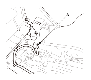
8141D0
Removal
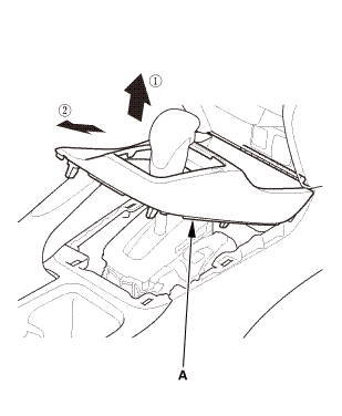
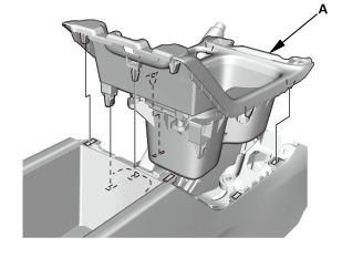
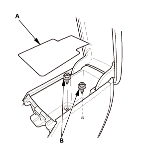
1.
Moonroof Link Cover Both
1.
Remove the lid (A).
...
Removal
1.
Battery Terminal (SRS) - Disconnection
1.
Make sure the ignition switch is in LOCK (0).
...


 Moonroof Drain Channel Removal and Installation (4-door)
 Moonroof Frame/Drain Channel Slider and Cable Assembly Removal and Installation
(2-door)
Moonroof Frame/Drain Channel Slider and Cable Assembly Removal and Installation
(2-door)