Honda Civic manuals

Honda Civic Service Manual: FTT Sensor Removal and Installation (R18A9)

Honda Civic Service Manual / Powertrain / Engine / Fuel System / Fuel Tank / FTT Sensor Removal and Installation (R18A9)

310109

1. Vehicle Lift

1.

Raise the vehicle on a lift, and make sure it is securely supported.


2. Fuel Pressure - Relieving (Between the fuel tank and the engine) (Natural Gas Model)


Compressed natural gas is flammable and highly explosive. You could be killed or seriously injured if leaking natural gas is ignited.
Stop the engine, and keep heat, sparks, and flames away.


This procedure should be done outside in a well-ventilated area or in a properly equipped CNG shop.


This procedure will allow you to safely work on any part of the fuel system downstream of the fuel tank such as the fuel joint block or the manual shut-off valve.


NOTE: Make sure the manual shut-off valve is open.


1.

Remove the rear seat.


2.

Remove the seat back.


3.

Disconnect the connector (A) (this prevents the tank from supplying fuel to the system).


4.

Start the engine, and let it idle.


5.

After a few minutes, the engine will stall.


6.

Turn the ignition switch to LOCK (0).


3. Rear Floor Undercover (Natural Gas Model)

1.

Remove the rear floor undercover (A).


4. Fuel Pipes at the Fuel Joint Block (Natural Gas Model)

1.

Remove the three fuel pipes (A) at the fuel joint block (B) and the two fuel joint block mounting bolts (C).


NOTE: Always use two wrenches when removing fuel pipe nuts.


5. Lower The Vehicle On The Lift

1.

Lower the vehicle on the lift.


6. Left Rear Door Panel Assembly (Natural Gas Model)

1.

Remove the left rear door assembly (A).


2.

Disconnect the connector (A).


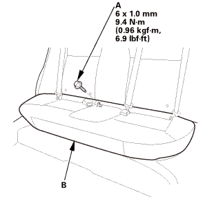
7. Rear Seat Cushion

1.

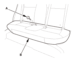
Remove the bolt (A) securing the rear seat cushion (B).


2.

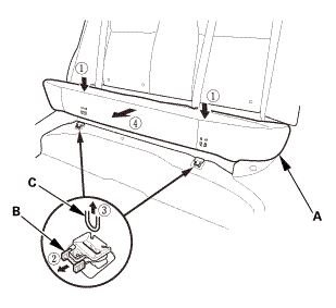
While pushing down the rear seat cushion (A), pull the seat hook handles (B) to release the hooks (C).


3.

Remove the rear seat cushion.


8. Center seat belt buckle bolt

1.

Remove the center seat belt buckle bolt (A) at the floor.


9. Rear Seat-Back (Natural Gas Model)

1.

Release the center seat belt (A) from the center belt guide (B).


2.

Remove the bolts (A).


3.

Remove the rear seat-back (A).


10. Both C-Pillar Trims


1.

Pull out the C-pillar trim (A) to release the clips.


2.

Remove the C-pillar trim.


NOTE: The front clip (B) will stay in the body.


3.

The left side is shown; repeat on the right side.


4.

Remove the front clip (A).


5.

The left side is shown; repeat on the right side.


11. Rear Shelf (Natural Gas Model)

1.

From the trunk compartment, disconnect the connector (A).


2.

From the trunk compartment, detach the clips (A).


3.

Pull out both rear seat belts (A) and the rear center seat belt (B) through the slits in the rear shelf trim (C), then remove the rear shelf trim.


12. Trunk Floor Lid (Natural Gas Model)

1.

Remove the trunk floor cover (A).


13. Trunk Front Trim Panel (Natural Gas Model)

1.

Remove the trunk front trim panel (A) and the trunk partition (B) as an assembly.


14. Fuel Tank Protector (Natural Gas Model)

1.

Remove the fuel tank protector (A).


15. Rear Bulkhead Gusset Both Sides (Natural Gas Model)

1.

Remove the gussets (A).


16. Rear Parcel Cover (Natural Gas Model)

1.

Disconnect the speaker connectors, and remove the rear parcel cover (A).


17. Rear Shelf Gusset Both Sides (Natural Gas Model)

1.

Remove the rear shelf gussets (A) in the trunk.


18. Rear Floor Upper Crossmember Gusset (Natural Gas Model)

1.

Remove the rear floor upper crossmember gusset (A).


19. Fuel Tank Assembly (Natural Gas Model)

1.

Remove the bolts (A).


2.

Disconnect the vent hose (A).


3.

Remove the tank frame mounting bolts (A).


4.

Push the front seats forward, then cover the seats and the floor with a tarp or similar material.


5.

With the help of two other technicians, lift the frame, and slide the entire fuel tank assembly (A) into the passenger compartment. Be careful not to damage the fuel joint block.


6.

Rotate the fuel tank so the fuel joint block and the frame can clear the left rear door opening, then carefully remove the fuel tank assembly from the vehicle.


20. Fuel Pipe Duct (Natural Gas Model)


1.

Remove the harness clamp (A).


2.

Remove the fuel pipe duct (B).


3.

Disconnect the connector (C).


4.

Remove the fuel pipes (D) from the fuel tank.


NOTE: Always use two wrenches when removing the fuel line nuts.


21. Fuel Joint Duct (Natural Gas Model)


1.

Remove the fuel joint duct (A) and the fuel pipes (B).


NOTE: Always use two wrenches when removing the fuel pipe nuts.


2.

Disconnect the connectors (C).


22. FTT Sensor (Natural Gas Model)

1.

Remove the FTT sensor (A).


1. Fuel Pipe Connector O-Ring (Natural Gas Model)

1.

Wrap vinyl tape around the threads, and coat the surface of the tape with silicone oil or grease.


NOTE: Wrap the vinyl tape (A) so that there is no stepped portion.


2.

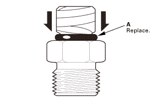
Install a new O-ring (A) into the groove.


NOTE: Be careful not damage the sealing face of the O-ring.


3.

Using a small brush, apply silicone oil or grease to the outer surface of the O-ring.


4.

Remove the vinyl tape.


2. FTT Sensor (Natural Gas Model)


1.

Apply silicone oil or polyalkyleneglycol (PAG) oil to a new O-ring (A), and carefully install it into its proper position.


2.

Install the FTT sensor (B) with a new O-ring.


3. Fuel Joint Duct (Natural Gas Model)


1.

Connect the connectors (A).


2.

Install the fuel pipes (B) with new O-Rings (C) and the fuel joint duct (D).


NOTE: Always use two wrenches when installing the fuel pipe nuts.


4. Fuel Pipe Duct (Natural Gas Model)


1.

Install the fuel pipes (A) from the fuel tank with new O-rings (B).


NOTE: Always use two wrenches when installing fuel pipe nuts.


2.

Connect the connector (C).


3.

Install the fuel pipe duct (D).


4.

Install the harness clamp (E).


5. Fuel Tank Assembly (Natural Gas Model)


1.

With the help of two other technicians, lift the frame, and slide the entire fuel tank assembly (A) into the passenger compartment from outside the vehicle. Be careful not to damage the fuel joint block.


2.

Carefully set the fuel tank assembly to the proper position.


3s

3.

Install the tank frame mounting bolts (A).


4.

Connect the vent hose (A).


5.

Install the bolts (A).


6. Rear Floor Upper Crossmember Gusset (Natural Gas Model)

1.

Install the rear floor upper crossmember gusset (A).


NOTE:

Tighten the bolts by hand first, then tighten them to the specified torque.

Tighten the bolts to the specified torque in the sequence shown.


7. Rear Shelf Gusset Both Sides (Natural Gas Model)

1.

Remove the rear shelf gussets (A) in the trunk.


8. Rear Parcel Cover (Natural Gas Model)

on

1.

Install the rear parcel cover (A), and reconnect the speaker connectors.


9. Rear Bulkhead Gusset Both Sides (Natural Gas Model)

22

1.

Install the gussets (A).


10. Fuel Tank Protector (Natural Gas Model)

1.

Install the fuel tank protector (A).


11. Trunk Front Trim Panel (Natural Gas Model)

1.

Install the trunk front trim panel (A) and the trunk partition (B) as an assembly.


12. Trunk Floor Lid (Natural Gas Model)

1.

Install the trunk floor cover (A).


13. Rear Shelf (Natural Gas Model)

1.

Slip the rear seat belts (A) and the rear center seat belt (B) through the slits in the rear shelf trim (C).


2.

Install the clips (A).


3.

From the trunk compartment, connect the connector (A).


14. Both C-Pillar Trims

1.

Install the new front clip (A) to the C-pillar trim (B).


2.

Install the C-pillar trim (A).


NOTE:

Make sure the side curtain airbag is not tucked under the clips or the ribs.

Do not push too hard on the C-pillar trim. If you push too hard, the clip will be damaged, and it will not hold the trim properly.

Gently tug on the C-pillar trim to verify that all clips are securely fastened.


3.

The left side is shown; repeat on the right side.


15. Rear Seat-Back (Natural Gas Model)

1.

Install the rear seat-back (A).


m.imim

2.

Install the bolts (A).


3.

Install the center seat belt (A) to the center belt guide (B).


16. Center seat belt buckle bolt

32

1.

Install the center seat belt buckle bolt (A).


17. Rear Seat Cushion

1.

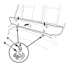
Install the hooks (A) to the rear seat cushion clips (B).


2.

Install the bolt (A) securing the rear seat cushion (B).


18. Left Rear Door Panel Assembly (Natural Gas Model)

1.

Connect the connector (A).


2.

Install the left rear door assembly (A).


19. Door Position - Adjustment (4-door)

Front

mm


Rear


NOTE: Check for a flush fit with the body, then check for equal gaps between the front and rear doors, and between the doors, and the body. Check that the door and body edges are parallel.


1.

Place the vehicle on a firm, level surface when adjusting the doors.


2.

Adjust at the hinges:


Pad a floor jack with shop towels, then use the jack to support the door while adjusting it.

Loosen the hinge mounting bolts (A) slightly, and move the door backward or forward, up or down as necessary to equalize the gaps.


3.

If necessary, replace the door mounting bolts with the adjusting bolts made specifically for door adjustment, then adjust at the door: Loosen the door mounting bolts (B) slightly, and move the door up or down as necessary to equalize the gaps, and move it in or out until it's flush with the body.


NOTE: Refer to the Parts Catalog if you need use an adjusting bolt.


4.

Check that the door and body edges are parallel. If necessary, adjust the door cushions (A) to make the rear of the doors flush with the body.


5.

Apply touch-up paint to the hinge mounting bolts, and around the hinges.


20. Fuel Pipes at the Fuel Joint Block (Natural Gas Model)

-.25u....m.2n


1.

Install two fuel joint block mounting bolts (A).


2.

Install the three fuel pipes (B) at the fuel joint block (C).


NOTE: Always use two wrenches when installing fuel pipe nuts.


21. Rear Floor Undercover (Natural Gas Model)

ioumm

1.

Install the rear floor undercover (A).


22. Manual Shut-off Valve - Open (Natural Gas Model)

1.

Open the manual shut-off valve (A).


23. Fuel Supply System Leak - Inspection (Natural Gas Model)

Check for a gas leak if there is an odor coming from the vehicle. Compressed natural gas (CNG) can only be smelled, not seen.


1.

Open the hood and the fuel fill door.


2.

Connect a vacuum pump/gauge, 0-30 inHg, to the hose (A) from fuel pressure regulator P1, and apply 67.7 kPa (20.0 inHg, 508 mmHg) of vacuum.


3.

If fuel pressure regulator P2 does not hold vacuum, replace it before continuing to the next step.


4.

Inspect the fuel lines and hoses under the hood for kinks, abrasion, and other signs of damage.


5.

With the manual shut-off valve open, turn the ignition switch to ON (II), but do not start the engine.


6.

After the fuel pressure regulator shut-off solenoid valve/fuel tank internal solenoid valve operates for about 2 seconds, the fuel pressure in the fuel lines rises.


7.

Turn the ignition switch to LOCK (0).


8.

Repeat this two or three times.


9.

Within 1 minute, check for any damaged lines with a leak detector (A) (Snap-on Combustible Gas Leak Detector or Snoop Liquid Leak Detector (B)).


10.

If no damage was noticed during the inspection, turn the ignition switch to ON (II) for 2 seconds, then turn the ignition switch to LOCK (0).


11.

Within 1 minute, check for a leak at the vent hose outlet inside the fuel pipe protector (A).


12.

If you detect a leak, remove the vent hose, and check the fuel lines and fittings at the in-tank solenoid valve and the join block with a leak detector.


13.

If you cannot find the leak, raise the vehicle on a lift, remove the under-floor cover.


14.

Inspect all the fuel lines under the vehicle, visually, and with a leak detector.


15.

If you still cannot find the leak, remove the rear seat, then check all fuel lines and fittings at the fuel tank and the fuel joint block.


Fuel Tank
...

Fuel Tank Draining (K24Z7)
Removal 1. HDS DLC - Connection NOTE: For specific operations, refer to the user's manual that came with the Honda Diagnosti ...

See also:

Honda Civic Owners Manual. Customizing the Meter
You can edit, add, or delete the meter contents on the driver information interface. 1. 2. Settings 3. System 4. Configuration of Instrument Panel Customizing the Meter You can store up to three customized configurations. To select or customize a configuration, press Swap Config.. ...

© 2016-2024 Copyright www.hocivic.com

0.0082