Honda Civic Service Manual: Carpet Removal and Installation (2-door A/T)
847100

|
SRS components are located in this area. Review the SRS component locations
and the precautions and procedures before doing repairs or service.
|
| 1. |
Battery Terminal (SRS) - Disconnection |
|

|
|
1.
|
Make sure the ignition switch is in LOCK (0).
|
|
2.
|
Disconnect and isolate the negative cable with the battery sensor
(A) from the battery.
|
|
NOTE:
|
|

|
Always disconnect the negative side first.
|
|
|
|
To protect the battery sensor connector (B) from
damage, do not hold it when removing the negative
terminal.
|
|
|
|
Do not disconnect the battery sensor from the
negative terminal (C).
|
|
|
|
3.
|
Disconnect the positive cable (D) from the battery.
|
|
4.
|
Wait at least 3 minutes before starting work.
|
|
| 2. |
Both Front Seat Belt Lower Anchor Bolts |
|
Driver's side

Passenger's side

|
|
1.
|
Remove the lower anchor cap (A).
|
|
2.
|
Remove the lower anchor bolt (B).
|
|
|

|
|
1.
|
Remove both seat track end covers (A).
|
|
2.
|
The driver's seat is shown; repeat on the passenger's seat.
|
|
|
Front side

Rear side

|
|
3.
|
Remove the seat mounting bolts (A).
|
|
4.
|
The driver's seat is shown; repeat on the passenger's seat.
|
|
|

|
|
5.
|
Disconnect the connectors (A).
|
|
6.
|
Detach the harness clips (B).
|
|
7.
|
The driver's seat is shown; repeat on the passenger's seat.
|
|
8.
|
With the help of an assistant, carefully remove both front seats
through the front door opening.
|
|
|
|
|
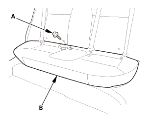
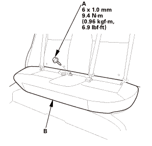
1.
|
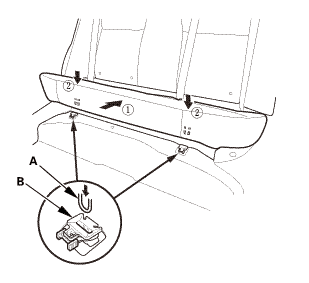
Remove the bolt (A) securing the rear seat cushion (B).
|
|
|
|
|
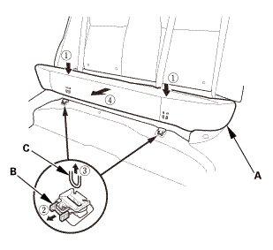
2.
|
While pushing down the rear seat cushion (A), pull the seat hook
handles (B) to release the hooks (C).
|
|
3.
|
Remove the rear seat cushion.
|
|
| 5. |
Front Door Sill Trim - 2-Door |
|

|
|
2.
|
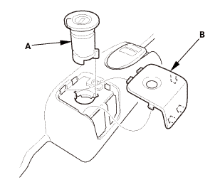
Remove the opener lock cylinder (B).
|
|
|

|
|
4.
|
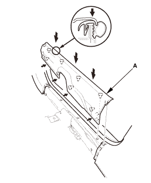
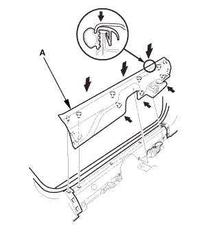
Remove the front door sill trim (A).
|
|
| 6. |
Front Door Sill Trim - 2-Door |
|

|
|
1.
|
Remove the front door sill trim (A).
|
|
|
Driver's side

Passenger's side

|
|
1.
|
Pull out both front door opening seals (A) as needed.
|
|
2.
|
Remove both kick panels (B).
|
|
| 8. |
Center Console Panel Assembly (Except '12M M/T) |
|

|
|
2.
|
Remove the center console panel (A).
|
|
3.
|
For some models: Disconnect the connector(s) (B).
|
|
| 9. |
Cup Holder Panel Assembly |
|
|
|
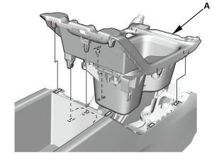
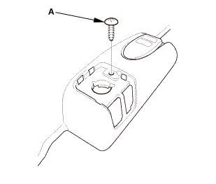
1.
|
Remove the cup holder panel assembly (A).
|
|
|
|
|
2.
|
Disconnect the connector (B).
|
|
|
|
|
3.
|
Remove the console box mat (A).
|
|
|
|
|
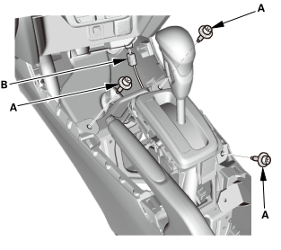
5.
|
Disconnect the connector (A).
|
|
|

|
|
6.
|
Remove the center console (A).
|
|
|

|
|
1.
|
Remove the steering joint cover (A).
|
|
|

|
|
1.
|
Remove the lower clip (A) from the stud bolt (B) with a 6 mm
hex socket wrench.
|
|
2.
|
Remove the upper clip (C) from the stud bolt (D) with a flat-tip
screwdriver, then remove the footrest (E).
|
|
| 13. |
Floor Carpet - 2-Door (A/T) |
|

|
|
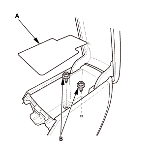
1.
|
Remove the HVAC bracket (A).
|
|
|

|
|
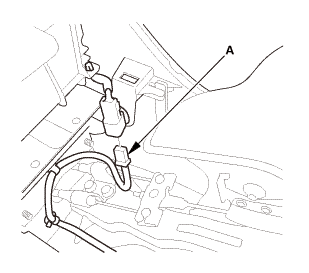
2.
|
Disconnect the connectors (A), and detach the harness clips (B).
|
|
|

|
|
3.
|
Detach the harness clips (A).
|
|
|

|
|
5.
|
Release the hook and loop fastener (B).
|
|
6.
|
Cut the carpet (C) in the area (D) as shown.
|
|
7.
|
Pull out the seat harnesses (E), then remove the carpet.
|
|
|

|
|
8.
|
If necessary, remove the floor mat holder (A).
|
|

|
SRS components are located in this area. Review the SRS component locations
and the precautions and procedures before doing repairs or service.
|
| 1. |
Floor Carpet - 2-Door (A/T) |
|

|
|
1.
|
If necessary, install the floor mat holder (A).
|
|
|

|
|
2.
|
When installing the new carpet, cut the carpet in the area (A)
as shown.
|
|
3.
|
Pass the seat harnesses (B), then install the carpet (C).
|
|
4.
|
Install the hook and loop fastener (D).
|
|
5.
|
Install the clips (E).
|
|
|
|
|
6.
|
Install the harness clips (A).
|
|
|
|
|
7.
|
Connect the connectors (A), and install the harness clips (B).
|
|
|

|
|
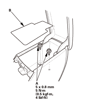
8.
|
Install the HVAC bracket (A).
|
|
|

|
|
1.
|
Install the upper clip (A) to the stud bolt (B).
|
|
2.
|
Install the lower clip (C) to the stud bolt (D), then install
the footrest (E).
|
|
|

|
|
1.
|
Install the steering joint cover (A) in the sequence shown.
|
|
|

|
|
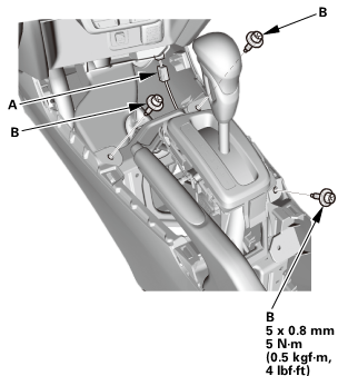
1.
|
Install the center console (A).
|
|
|
|
|
2.
|
Connect the connector (A).
|
|
|
|
|
3.
|
Install the bolts (A).
|
|
4.
|
Install the console box mat (B).
|
|
|
|
|
5.
|
Connect the connector (A).
|
|
6.
|
Install the bolts (B).
|
|
| 5. |
Cup Holder Panel Assembly |
|
|
|
1.
|
Install the cup holder panel assembly (A).
|
|
| 6. |
Center Console Panel Assembly (Except '12M M/T) |
|

|
|
1.
|
For some models: Connect the connector(s) (A).
|
|
2.
|
Install the center console panel (B).
|
|
|

|
|
3.
|
Install the clips (A).
|
|
|
Driver's side

Passenger's side

|
|
1.
|
Install both kick panels (A).
|
|
2.
|
Install both front door opening seals (B) as needed.
|
|
| 8. |
Front Door Sill Trim - 2-Door |
|
|
|
1.
|
Install the front door sill trim (A).
|
|
| 9. |
Front Door Sill Trim - 2-Door |
|
|
|
1.
|
Install the front door sill trim (A).
|
|
|

|
|
2.
|
Install the screw (A).
|
|
|
|
|
3.
|
Install the opener lock cylinder (A).
|
|
|
|
|
1.
|
Install the hooks (A) to the rear seat cushion clips (B).
|
|
|
|
|
2.
|
Install the bolt (A) securing the rear seat cushion (B).
|
|
|
|
|
1.
|
With the help of an assistant, carefully install both front seats
through the front door opening.
|
|
2.
|
Install the harness clips (A).
|
|
3.
|
Connect the connectors (B).
|
|
4.
|
The driver's seat is shown; repeat on the passenger's seat.
|
|
|
Front side
 1n25mman 1n25mman
Rear side

|
|
5.
|
Install the seat mounting bolts (A).
|
|
NOTE: Tighten the bolts to the specified torque in the sequence
shown.
|
|
|
Tighten the bolts by hand first, then tighten
them to the specified torque.
|
|
|
|
Tighten the seat mounting bolts to the specified
torque in the sequence shown. Slide the seat all
the way back and tighten 1 and 2, then slide it
forward and tighten 3 and 4.
|
|
|
|
6.
|
The driver's seat is shown; repeat on the passenger's seat.
|
|
|

|
|
7.
|
Install both seat track end covers (A).
|
|
8.
|
The driver's seat is shown; repeat on the passenger's seat.
|
|
| 12. |
Both Front Seat Belt Lower Anchor Bolts |
|
Driver's side

Passenger's side
 @@@ @@@
|
|
1.
|
Assemble the washer, the collar, and the bushing on the lower
anchor bolt as shown.
|
|
NOTE: Apply medium strength liquid thread lock to the lower anchor
bolt before reinstallation.
|
|
|
Driver's side
 7m2nmn:mm 7m2nmn:mm
Passenger's side
 unr:2inm, unr:2inm,
|
|
2.
|
Install the lower anchor bolt (A).
|
|
3.
|
Install the lower anchor cap (B).
|
|
| 13. |
Battery Terminal (SRS) - Reconnection |
|
 (o.2ao.sam. (o.2ao.sam.
|
|
NOTE: If the battery performs abnormally, test the battery.
|
|
1.
|
Clean the battery terminals.
|
|
2.
|
Connect the positive cable (A) to the battery.
|
|
NOTE: Always connect the positive side first.
|
|
3.
|
Connect the negative cable and the battery sensor (B) to the
battery.
|
|
NOTE: To protect the battery sensor connector (C) from damage,
do not hold it when installing the negative terminal.
|
|
4.
|
Apply multipurpose grease to the terminals to prevent corrosion.
|
|
847100
SRS components are located in this area. Review the SRS component locations
and the precautions and procedures before doing repairs or service.
1.
Bat ...
See also:
Honda Civic Owners Manual. Brightness Control
When the parking lights are turned on and the
ignition switch is in ON *1, you can
use the
brightness control knob to adjust instrument
panel brightness.
Brighten: Turn the knob to the right.
Dim: Turn the knob to the left.
You will hear a beep when the brightness
reaches minimum or ...

 Carpet Removal and Installation (4-door A/T)